Description
Code Setting and Installation Instructions
Description
The digital receiver and transmitter is a single-channel wireless radio control designed for use with automatic garage/ gate operators and access control systems. All products (on the same frequency) can be mixed and matched to suit your individual needs.
The radio format provides 256 different digital codes. The codes are set using the 8-position coding switches in the units.
Caution: All transmitters and receivers should be recoded prior to operation.
In order to avoid the possibility of duplicating codes in adjacent systems, factory set codes should not be used. In addition, among the valid codes available, four others should not be used. These include: all keys set ON or OFF and keys set alternating ON/ OFF.
Where a number of receivers are to be installed in close proximity ( as in an apartment complex), install receivers at least 5 feet apart. If receivers are installed closer than 5 feet apart, blocking may occur.
After completing an installation, operate the transmitter outside the building and check to see that the coded signal being used does not interfere with neighboring garage door operators and/ or security systems. If interference is detected, select another code and check coded signal again. Repeat if necessary.
Step 1 Locate Coding Switches.
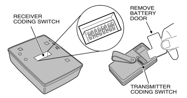
Locate the digital coding switch for the receiver which is recessed in the center of the back of the case. The transmitter coding switch is accessed by removing the battery access door located on the back of the transmitter case. The keys are numbered 1 through 8. The switches in the receiver must match the switches in all transmitters used to operate the receiver.

Step2 Code Transmitter and Receiver.
Use a paper clip or other pointed object (except a pencil or pen) to pick any combination of ON/ OFF codes and set them on switch keys 1 through 8 on the receiver and transmitter. The ON position is when the top of the switch is down. The OFF position is when the top of the switch is up and the bottom is down.

Step3A Connecting Receiver ( Using transformer power).
Where it is not feasible to obtain power from the operator, connect a Model 524 transformer ( Accessory) to the receiver as shown below. Then Plug the transformer into a convenient ( Un-switched) 110 VAC outlet.

Step3B Connecting receiver (using operator power).
Connect the receiver to the garage door or gate operator as shown in the diagram. Power will be supplied from the operator.

Step4 Remote Mounting.
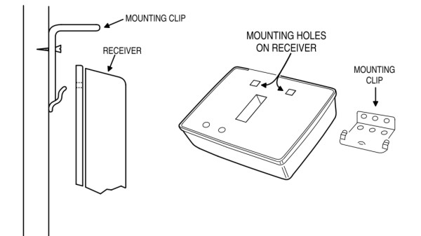
A mounting clip is packaged with each receiver. To install the receiver, attach the clip to the mounting surface with screws. Position the two rectangular holes on the back of the receiver over the clip and snap the receiver down into place.

Transmitter and Receiver: SKU 112023
Transmitter only: SKU 112018


